
Why Electrical Testing Instruments Matter for Engineers
Electrical engineers rely on precision and accuracy when dealing with electrical systems. The right testing instruments are essential for ensuring safety, efficiency, and long-term reliability in electrical installations. Whether you’re designing complex circuits or maintaining existing infrastructure, having the proper tools at your disposal is critical.
This guide delves into the top 10 electrical testing instruments every engineer should know, providing valuable insights into their functions, applications, and real-world usage. By the end of this article, you will have a comprehensive understanding of these essential tools, helping you make informed decisions for your work.
Table of Contents
- Multimeter
- Clamp Meter
- Insulation Resistance Tester
- Power Quality Analyzer
- Oscilloscope
- Circuit Analyzer
- Earth Ground Tester
- Cable Tester
- Voltage Tester
- Function Generator

Image Source: Hioki Official
1. Multimeter
What It Is
The multimeter is one of the most versatile electrical testing instruments. It measures voltage, current, and resistance, making it indispensable for almost every electrical engineer.
How It Helps Engineers
In the field, the multimeter is used to troubleshoot circuits, check battery voltage, and measure continuity. Its versatility makes it an essential tool for any project, from simple residential electrical work to more complex industrial applications.
Real-World Example
In a recent project, an engineer used a multimeter to quickly identify a faulty wire in a residential circuit, saving time and resources.
Key Features to Look for
- Digital vs. Analog: Digital meters offer higher accuracy and ease of use.
- Display: Ensure the display is large and readable, especially in low-light conditions.
- Auto-ranging: This feature allows the multimeter to automatically select the appropriate range, making it easier to use.
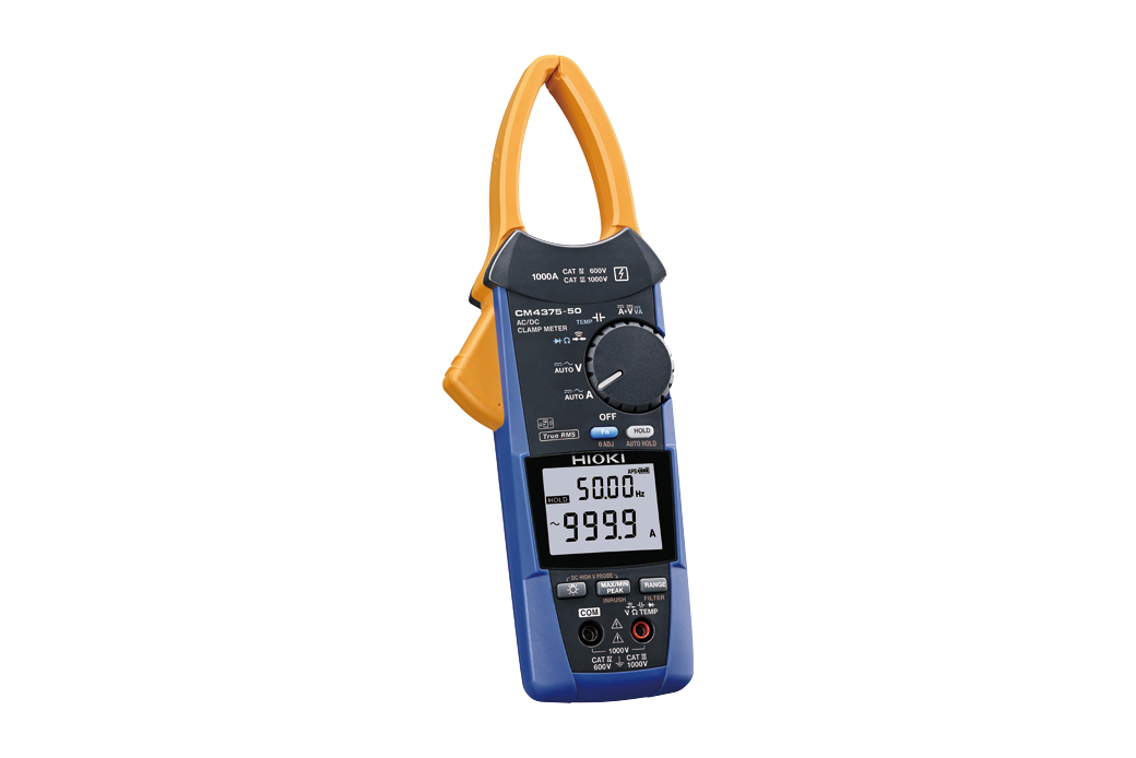
Image Source: Hioki Official
2. Clamp Meter
What It Is
A clamp meter is designed to measure current without needing to disconnect the circuit. It uses a clamping mechanism to encircle a conductor, detecting the current flow through electromagnetic induction.
How It Helps Engineers
Clamp meters are especially useful in high-voltage environments or when working with systems where direct contact with wires is unsafe or impractical.
Real-World Example
When working on a power grid, an engineer used a clamp meter to measure current in a live wire safely, ensuring compliance with safety standards.
Key Features to Look for
- AC/DC Measurement: Choose a clamp meter that can measure both AC and DC currents for versatility.
- Jaw Size: The jaw size should accommodate the thickness of cables you frequently work with.
- Accuracy: Look for a meter that provides precise readings, especially in large installations.
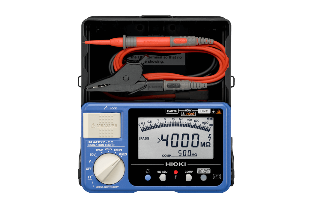
Image Source: Hioki Official
3. Insulation Resistance Tester
What It Is
This device measures the integrity of insulation in electrical wiring and equipment. It applies a high voltage to the insulation and measures how much current leaks through.
How It Helps Engineers
Insulation testers are crucial for ensuring safety in electrical systems, particularly in older installations where insulation can degrade over time. It helps prevent electrical fires and equipment failure.
Real-World Example
An engineer working on a commercial building used an insulation resistance tester to ensure the electrical wiring was safe before energizing the system.
Key Features to Look for
- Test Voltage Range: Higher test voltages allow for testing in a wider range of scenarios.
- Long Battery Life: Insulation testers often require prolonged usage in the field, so battery life is important.
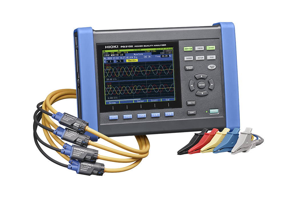
Image Source: Hioki Official
4. Power Quality Analyzer
What It Is
A power quality analyzer measures fluctuations and disturbances in the electrical power supply, such as voltage sags, surges, and harmonics.
How It Helps Engineers
These devices are essential for identifying power quality issues in industrial and commercial systems, which can affect equipment performance and lifespan.
Real-World Example
In an industrial plant, a power quality analyzer was used to detect harmonic distortion caused by large motors, allowing the engineers to take corrective actions and protect sensitive equipment.
Key Features to Look for
- Real-Time Data: Look for analyzers that provide real-time monitoring of power quality parameters.
- Data Logging: Ensure the device has ample memory for recording long-term power quality trends.
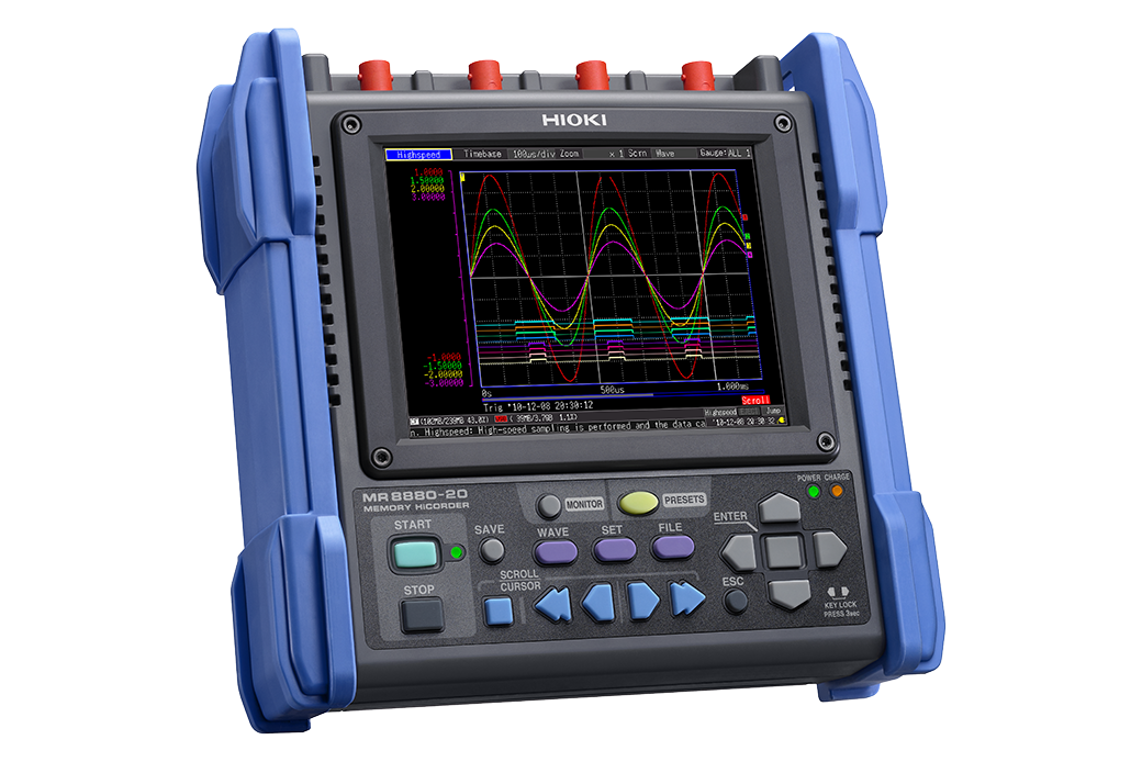
Image Source: Hioki Official
5. Oscilloscope
What It Is
An oscilloscope displays voltage signals over time, allowing engineers to observe the waveform of electrical signals in real time.
How It Helps Engineers
Oscilloscopes are indispensable when diagnosing complex issues like signal distortion, oscillation frequency, or troubleshooting circuits with varying frequencies.
Real-World Example
An engineer used an oscilloscope to troubleshoot a malfunctioning circuit in a microprocessor, identifying noise in the signal that was affecting performance.
Key Features to Look for
- Bandwidth: Ensure the oscilloscope’s bandwidth covers the frequencies you work with.
- Channel Count: Multiple channels allow you to observe different signals simultaneously.

Image Source: Hioki Official
6. Circuit Analyzer
What It Is
A circuit analyzer is a tool that evaluates the performance of electrical circuits, checking for wiring faults, open or short circuits, and grounding issues.
How It Helps Engineers
It’s primarily used to verify the quality and integrity of electrical installations, ensuring everything is wired correctly and safe.
Real-World Example
A circuit analyzer was used in a home renovation project to ensure the new electrical system met local codes and was functioning properly before powering up the home.
Key Features to Look for
- Fault Detection: Ensure the analyzer is capable of detecting all potential faults, including grounding and open/short circuits.
- Compliance: Look for devices that are certified to meet local electrical standards.
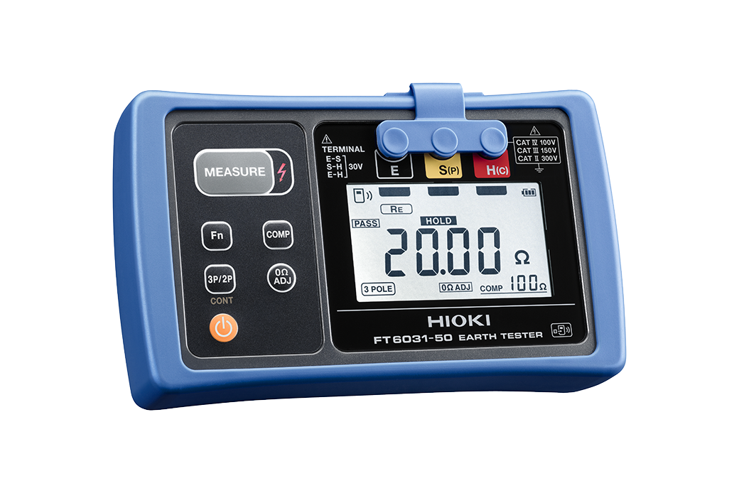
Image Source: Hioki Official
7. Earth Ground Tester
What It Is
An earth ground tester ensures that electrical systems are properly grounded, which is crucial for preventing electric shock hazards.
How It Helps Engineers
Used in residential, commercial, and industrial applications, this tool helps engineers verify that a grounding system is working efficiently.
Real-World Example
In a large office building, the earth ground tester was used to check the ground resistance of the building’s electrical system, ensuring that it complied with safety regulations.
Key Features to Look for
- Test Range: Ensure the tester is suitable for the specific ground resistance levels in your environment.
- Accuracy: Precise readings are crucial, particularly in installations with sensitive equipment.
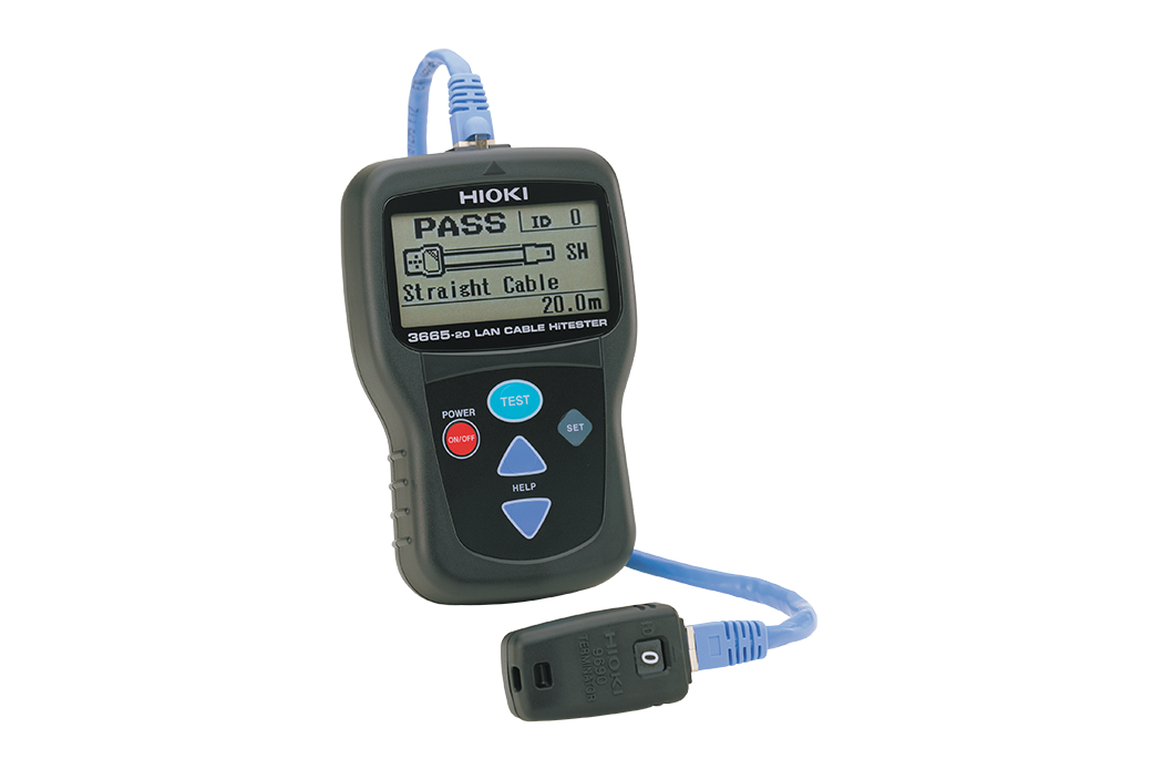
Image Source: Hioki Official
8. Cable Tester
What It Is
A cable tester checks the functionality and integrity of electrical cables, ensuring they are properly connected and free of faults.
How It Helps Engineers
Engineers use cable testers to confirm that new installations or replacements are working as expected, reducing downtime caused by faulty wiring.
Real-World Example
Before installing a network system, an engineer used a cable tester to check the integrity of cables, preventing future communication failures.
Key Features to Look for
- Compatibility: Ensure the tester works with a variety of cable types (e.g., coaxial, Ethernet).
- Display: A clear, user-friendly display makes it easier to interpret the test results.
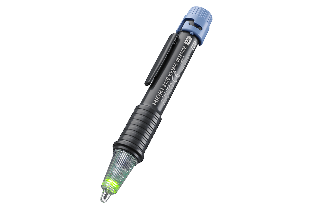
Image Source: Hioki Official
9. Voltage Tester
What It Is
A voltage tester is a simple, handheld device used to check for the presence of voltage in a circuit.
How It Helps Engineers
This tool helps engineers safely test electrical circuits before handling them, ensuring there’s no live current that could cause injury.
Real-World Example
An electrician used a voltage tester before working on a residential circuit to ensure it was safe to handle.
Key Features to Look for
- Non-Contact Design: This feature enhances safety by allowing engineers to detect voltage without direct contact.
- Visual and Audible Alerts: Look for testers that provide both visual and audible alerts to signal voltage presence.
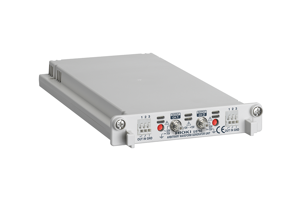
Image Source: Hioki Official
10. Function Generator
What It Is
A function generator creates a variety of waveforms, including sine, square, and triangular waves, which can be used to test circuits or simulate signals.
How It Helps Engineers
Function generators are essential for testing and troubleshooting circuits, especially those involving timing, modulation, or frequency-related issues.
Real-World Example
In a lab environment, a function generator was used to simulate sensor signals for testing a microcontroller’s response.
Key Features to Look for
- Frequency Range: Ensure the generator can produce the frequencies required for your work.
- Waveform Versatility: Look for devices that can generate a wide variety of waveforms for diverse testing scenarios.
Conclusion: Key Takeaways for Electrical Engineers
Electrical testing instruments are indispensable tools for ensuring safety, reliability, and efficiency in electrical systems. Whether you’re a novice or a seasoned engineer, understanding how each of these instruments works and when to use them can make all the difference in your projects.
Actionable Takeaway
Start by familiarizing yourself with these essential tools and incorporating them into your daily work routine. To stay ahead, keep learning and explore further resources on how to enhance your electrical testing skills.
Call to Action
Want to learn more about electrical engineering and stay updated with the latest tools and techniques? Read our Blogs for expert insights, tips, and the latest news in the electrical engineering field!